Wednesday, March 11, 2020

Revit Lookup


Introduction:

1. Revit lookup helps in the exploration of the Revit document.
2. One can look into geometrical properties (bounding box), location, material properties, element hierarchical data such as it's Family, FamilySymbol, type of element (structural/ architectural/electrical), category, parameters that define instance/type properties.
3. 90% of the time I used Revit look up, it is so essential to understand how one can use API to get the required information.

In this post, we will discuss, what kind of information we can get from Revit lookup.
And I will mention some use cases from my previous experience.

Installation:

Download the installer, it will place both add-in and dll files in addins folder of Revit: 

Notes:

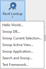
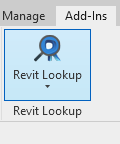
1. Revit Lookup is placed under the Add-Ins menu.
Once pressed the tab "Revit Lookup", it will expand and there will be multiple options to choose from.
To get information related to the document, select "Snoop DB" 
To get information related to an element, select "Snoop Current Selection"

Figure : (A)                               Figure : (B)
Selection and What information they provide?

(a) "Hello, World" - Gives the location of the Revit Lookup library(.dll) present in the system.

(b) "Snoop DB" - Gives the information related to the currently opened document.
It includes all :
- System families present in the document.
- External families present in a document
- Family Instances, Family types/symbols
- Views (project, system),  View families (Ceiling Plan, Floor Plan, Schedule)
- If the current document is a family document, there will be no views or other systems family.
It contains the number of extrusions/void elements depending upon the complexity of the family.
It contains geom-combination which represents the geometry of the family

(c) "Snoop Current Selection" - Gives information about selected eleemet.

I have created a Wall from System family. Family: Basic Wall, Type - Wall1
I will use these to snoop its properties.

Bounding Box - Represent the 3d box around an element. It gives diagonally opposite corners -  minimum and maximum points.

  • Category -  Represent the category of an element.
  • Geometry - Gives geometric representation of elements such as edges, faces, etc.
  • Id - Element Id
  • IsValidObject - Sometimes if the element gets deleted while some processing but we may still have element object and all its internal information is corrupted, in such case one can use whether the object is valid or not to process further else it will throw an exception while processing such elements.


    Figure : (C)  


  • Level Id - It gives the current Level's Id.
  • Location - It gives a location curve which contains information such as location point, curve, and rotation.
  • Parameters - It provides the instance/type parameters. They represent properties of instance/type.
  • for example Family, FamilyName, Category, Area, etc.
  • Parameters Map - I have never really used it. I don't really see the difference between Parameters and ParametersMap but most reliable is Parameters. Information will be the same in both but more consistent in Parameters.
  • UniqueId - Represent unique identifier of element.

    Figure : (D)  


  • GetOrderedParamters - It also provides the parameters same as Parameters field.

  • In this case, we have a Wall from family Basic Wall and type is Wall 1.
  • System family has its own family type/symbol such as WallType.
  • If we load a family into a document and created instance out of it then we have an element in the document. The element is FamilyInstance, its type would be FamilySymbol in terms of API but in case of system families we cannot cast elements type to FamilySymbol, instead, we can cast it to WallType if is a wall. At least it is true for the Wall family element as I observed.
  • GetTypeId - These provide the type id of the currently selected wall.
  • GetValidTypes - List all valid types belongs to selected elements Family.
    
                                                                    Figure : (E)  Represent Valid types for Wall family
  • WallType - If it were not a system family, then it would have been a little different. Instead of WallType, there would be the Family Symbol field. In both cases, it indicates the Type of family instance/element. If we select WallType, then we will be able to see the properties of WallType. Again the fields will be the same as the above fields, some fields would be additional in WallType window.
      • So RevitLook gives information in a hierarchy.
      • first is instance properties, second is type properties, third is family properties
      • System family properties would not be visible, but external loaded family properties would be visible.


Figure : (F)  Wall, Family Symbol/Type Properties


Figure : (G) Hierarchy Family Instance, symbol/type, family
*Family properties not visible in Revit Lookup for System family (from observation)


Figure : (H) Hierarchy Family Instance, symbol/type, family
*Family properties are visible in Revit Lookup for Externally family (from observation)


(D) "Snoop Active View"- These provide the current view information. Such as View3D/ViewPlan(sheet/2d views)  information. Both belongs to category Views.
In View3D, important fields are:
GetOrientation - Gives the Eye Position, ForwardDirection and UpDirection values in terms of vector. These values change if View3D changed from top, front, botttom, eight, left or any other possible orientation. These values can be used forgenerating views (iso, front, top views) for assembly.

(E) "Snoop Application" - Provides infomation related to active document, actyually application wide properties.

(F) "Search and Snoop" - Elements can be search and snoop using their ElementId and UniqueId.


Thanks!

Labels:

Sunday, November 3, 2019

Common Connection Edge Between Intersection Walls

Common Edges:


These post aim to find length of edge if the two adjacent walls have a common edge between them and also on which side of both the walls edge do exists (Right, Left, Top, Front, back).


Figure(1) : Common Edge between two connecting walls


Why do we need that ?

We could of it advantage like, edge between two intersection wall gives the length of path available for moving from wall a to wall b.

Example:
Figure(2) : Common Path that edge allows


How we can find it ?

Step1:
 Find intersecting walls. Represent walls by line.

Step2:
See one wall w.r.t other wall.

For example,
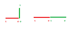
Figure(3): 2D walls connection
from figure(3),
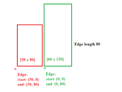
Red Wall - A,
Green Wall - B,
Both walls represented in line object.
Line object is represented by start and end point like a segments.
It can contains walls data such as wall height, thickness and direction.

Suppose we get the pair of intersecting line object and now to find the length of connecting edge
we can compare heights of two walls, whichever height is smallest we can use that height to find the
end point of path. So, till here we successfully calculated length of edge.

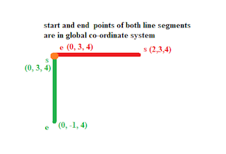
Figure(4) : Start and End point of edge
To find side of wall where edge is present.

We have to consider one of the endpoint (which is not intersecting) as origin.

For example,
in the below figure, if we consider red segment start point as origin then, 

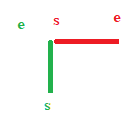
Figure(5) : Initially before considering origin 
Figure(6) : After considering a Red walls endpoint as a origin


Figure(7) : Rotating about point s by 180 deg


This is what it will be finally, we are basically translating everything by s and then rotating about s.

Now these what we needed to determine the side type of edge.
Left will always start from start point of wall.
Right will be at end point of wall.
Back will be when walls are not connected side to side but connected perpendicularly on back side,
Front will be when walls are not connected side to side but connected perpendicularly on front side,

For Wall A(red), side type of edge is Back,
For Wall B(green), side type of edge is Left,

Examples,

1)
Red Wall-> 
Edge Side Type - Left
Green Wall->
Edge Side Type - Right
Figure(8) : side to side
2) 
Red Wall->
Edge Side Type - Front
Green Wall->
Edge Side Type - Right
Figure(9) : side to front


Calculating length of Edge:
Figure(10) : side to side, calculate edge length

Thank you !


Labels:

Thursday, October 31, 2019

Coordinate Systems and Transformation

Coverting 2D problem to 3D problem:

Introduction: 

I am working on a project where i faced the issues with transformation and coordinate system.
Although, its not that difficult what it seems.

In these post, we will talk about coordinate systems and transformation in mathematical terms,
some code and considering some 3d model.

Rquirement:

Newtonsoft,
Math.net

We have:

3d co-ordinate system , 
2d co-ordinate system
Matrix for transformation, 
a 3d model to visualize

I will denote Co-ordinate system as co.

So in co, we usually use like 3d and 2d.
When we think of co in  3d, we will use XYZ as ploting points. e.g. pt(1,2,3) 
pt.X = 1, pt.Y = 2, pt.Z = 3

When we think of co in 2d we will use UV as ploting points. e.g. pt(1,2)
pt.U = 1, pt.V = 2


Lets consider a BIM model, a small house containing four walls, a ceiling.
3 Wall will have windows and 1 will have a door.
There are few electrical devices and a unit to power them.

I am considering these example to show the use of transformation in different co in real world scenario.


Yellow Wall w1 , win1
Orange Wall w2 , win2
Transparent Wall w3, door1

Lets consider a position which represents origin for our room. These position and room we will call it Unit. Unit is present in global co and same for all other elements.

Unit position in global context is (3,4,5)

Now for all Walls, consider they are in context of unit. So unit will be their origin (0,0,0).
We will identify them as they are in unit system (usys) (XYZ).

Now consider, window and door. We will define walls as their co. And wall edges represent their axis, hence they are in 2d system (UV). So whenever we talk about co of window it is a panel co (psys).

So now we have multiple co.
1. Global co (gsys)
2. Unit co (usys)
3. Panel co (psys)

These list can go on based on the identifying origins we want to use.

To interpret in best way, we would say:

We have a unit in gsys.
We have few walls in usys.
We have few windows and doors in psys.


Transformation:

More correctly we should say Affine Transformation.
It mean, it preserves geometrical meaning even after performing mathematical operations.
Simple wiki search will give you different types of transformations.
We are going to use Translation and Rotation.
Translation: Moving coordinates
Rotation: Rotating coordinates

Simple Example:


Figure(A) inital positions


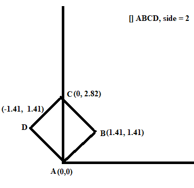
Consider a simple square []ABCD, side length = 2 m.
We will perform traslation and rotation on these square.

step 1:

Considering translation and rotation about point A.
translation by 1 m and rotation by 45 deg.


step 2:

Convert all points position w.r.t point A.
hence,

old   = O (0, 0), A(2, 1), B(4, 1), C(4, 3), D(2, 3)
new  = O(-2, -1), A(0, 0), B(2, 0), C(2, 2), D(0, 2)

so basically A is now our new origin or A is shifted to origin


Figure(B) : new positions

step 3:

Applying rotation.

In two dimensions, the standard rotation matrix has the following form,
.
This rotates column vectors by means of the following matrix multiplication,
a) Counter clockwise (+theta)


b) Clockwise (-theta)
.


We are going to rotate []ABCD in counter clockwise direction.
hence theta >=0;

Matrices are rowwise.
 M1 = R(45 deg) = [ [1, 1], [-1, 1] ]

M2 = [ [0, 2, 2, 0], [0, 0, 2, 2] ]

M3 = M2 * M1
       =  [ [0, 1.41, 0, -1.41] , [0, 1.41, 2.82, 1.41] ]

Figure(3) : rotation 45 deg counter clockwise


One thing we forget is translating the []ABCD by 1 m, till now we have translated to origin and rotated around origin.

We will translate by given value 1m in later in these post.
Till now, steps include:
1> Translate to origin
2> Rotate at origin

In mathematical formula both steps can be represent as :
Figure(4) : rotation matrix


a)  Represent translation by -x and -y towards origin
 b) Represent co-ordinates of []ABCD
When (a) and (b) both multiplied gives the traslation, 3rd row represent direction i guess and it helps in arithmetic operation.
Result of translation:


Result of rotation:


Now considering translation value = x = y =1 m,
so coodinates will change to
old   = O (0, 0), A(2, 1), B(4, 1), C(4, 3), D(2, 3)
new  = O(0, 0), A(1, 1), B(3, 0), C(3, 2), D(1, 2)

And to rotate about A, still we will need to translate to origin and then rotate.
hence here we are translating twice, first from old location to new location, second from new location to origin (second is required for rotation).

Matrix operation will look like:

Mat(from new position to old position) * Mat(from origin to new position) * Mat(rot at origin) * Mat(from new position to origin) * Mat(from old position to new position)

We multiple matrices in reverse order.
1. Translate to new position M1
2. Translate to origin from new position M2
3. Rotate at origin M3
4. Translate to new position from origin M4
4. Translate to old position from new position M5

M = M5*M4*M3*M2*M1

Rebuild From Hierarchical System.

These will give you the glimpse how the results of transformation will look like.

Hierarchical Co-ordinate transform:

Consider a unit with location coordinates as follows,
unit = [ 2110.0809, -220.7960, 216.1249] in global co-ordinate system

Consider a wall w.r.t unit as follows,
wallA = [ 12.975, -31.1827, -83.25] in unit co-ordinate system
wallA dimension = [663.5 (L), 109.125 (H), 7.25 (T)]

Consider a window w.r.t wall as follows,
windowA = [125.25, 64.125] in panel co-ordinate system
windowA dimension = [42.25, 60.25]

Figure(6) : 3d model representation for above mentioned data


only notable thing is wall start point itself becomes a origin and window position is calculated w.r.t it.
Wall boundaries become x and y axis.That means in panel system we only consider X and Y.

Building Hierarchical Configuration of Positions: 

Figure(7) : BIM Model (View 3D)
Bim model represent a wall, two blockages and a window.

Figure(8) : Wall central line (Top view of wall)

Fig(7) represent the 3d view on which we will work now. Basically i am just abandoning previously used room model and using these wall which is inside a room and consider some point as our unit origin.

Data:

Position:

Global origin co-ordinate: (0, 0, 0)-->(A)
Unit origin in global co-ordinate: (1, 1, 1)-->(B)
Panel origin in global co-ordinate: Start(1.3451, 12.1719, 0), End(11.6469, 12.1719, 0) -->(C)
1st Blockage origin in global co-ordinate: (4.8228, 12.1719, 6.5616) -->(D)
2nd Blockage origin in global co-ordinate: (10.9908, 12.2375, 6.5616) -->(E)
Window origin in global co-ordinate: (7.2506, 12, 6.7465) -->(F)

Converting to hierarchical form:

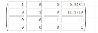
Panel w.r.t unit: ( 0.3451, 11.1719, -1)  --> using (B)&(C) -->(G)

1st Blockage w.r.t to Panel: (transition from XYZ to UV)
Z component will give us the V co-ordinate. Question is which one would be our U, X or Y of XYZ ?
That can be answered if we know whether wall is parallel to X or Y.

From Start and End point of wall, we can see that wall is parallel to X axis.
Hence our blockage position will have (X, Z) == (U, V)

Figure(9) :

(D) - (C) = (4.8228, 12.1719, 6.5616) - Start(1.3451, 12.1719, 0) = (3.4777, 0, 8.8817)
1st Blockage Position = (3.4777, 6.5616)
All four corners:
leftBottom = (3.3136, 0)
leftTop = (3.3136, 13.1233)
rightBottom = (3.6417, 0)
rightTop = (3.6417, 13.1233)

2nd Blockage w.r.t to Panel:
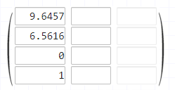
(E) - (C) = (10.9908, 12.2375, 6.5616) - Start(1.3451, 12.1719, 0) = (9.6457, 0.0656, 6.5616)
2nd Blockage Position = (9.6457,  6.5616)
All four corners:
leftBottom = (9.3176, 0)
leftTop = (9.3176, 13.1233)
rightBottom = (9.9738, 0)
rightTop = (9.97338, 13.1222)


Window w.r.t to Panel:
(F) - (C) = (7.2506, 6.7465) - (1.3451, 0) = (5.9055, 6.7465) 
Window Position = (5.9055, 6.7465)
All four corners:
leftBottom = (4.2651, 5.1041)
leftTop = (4.2651, 8.3849)
rightBottom = (7.5459, 5.1041)
rightTop = (7.5459, 8.3849)

Dimensions:
Panel = 
[L = 10.3018, T = 0.6562, H = 13.1233]

Blockage1 =
[L = 0.3281, T = 0.6562, H = 13.1233]

Blockage2 = 
[L = 0.6562, T = 0.5906, H=  13.1233]

Window = 
[L = 3.2808, T = 1, H = 3.2808]

Figure(10) : Blockage co-ordinates are in UV 2d w.r.t wall
Using Matrix:

A) For unit:
It is the simplest case we dont assume rotation about x axis = 0degree.
if there is rotation in unit itself w.r.t loadcenter then we have to add that rotation about x-axis suppose.In such case matrix will include rotation component and trignometric function used can change according to that.

B) For panel:
C) For blockage1:

D) For blockage2:

E) For window:


Now, how to use these matrices to reverse jump into global co-ordinates from their current coordinate system.
From particular co-ordinate system to global co-ordinate system:


For Panel->
 PanelToGlobal = (A) * (B) = 


For blockage1->

Blockage1ToGlobal =


For blockage2->
Blockage2ToGlobal =


For window->

WindowToGlobal =

Only converted the location point to global co-ordinate system


I guess these is enough for these post now. I want to cover, how we can draw complete shape after transforming to global co-ordinate system, because we only transformed the position. There is the thickness component haven't been considered yet.


Thanks!


Labels: ,

Sunday, September 29, 2019

The Revit API Introduction

Revit API Introduction:

Revit API provides access to properties, methods, interfaces to interact with Revit Elements.
How one can start using Revit API?

Motivation:

There are many resources out there that will give enough pointers to how to perform a specific task
using API. These posts only describe how to get started with using API.

There are lots of processes that can be accessed using API and can help you automate certain repetitive work. So, the main motivation of using API according to me is to automate most of these repetitive work. I have worked on such products. I extensively work with automation and optimization of Revit Models. The results were really effective and yes like many other products, they can still optimized to much more detail if followed some standards while designing a BIM model.

Getting Started:

1. To get started with Revit API, Autodesk provides Revit SDK that could be a really great resource to start with. But again for using API, everything boils down to basics of Revit and to know how Revit determines, differentiate between different elements in Revit document.
First thing I would suggest to use Revit, build  few walls, insert some family.

2. Once you get familiar with the Revit application. Install Revit Lookup, a much-needed piece for developers. Select any element in Revit Model and use Revit Lookup. It will give you geometric data,
location, rotation, category, family symbol, family and other information of selected element.
Read about family symbols, familyInstance, family, category. Try drawing a bounding box on paper obtained from the lookup.

3. Let's start with a simple hello world application/command.

4. The next step would be, get some simple Revit Model to play around.

  • Get a selection of an element from the Revit Model in API, extract information such as geometric data.
  • Geometric data includes the bounding box, faces, edges, etc. Get the location of the element. There can be different types of placement types of an element such as point-based, line/curve based, level-based, etc.
  • This information can be explored from Revit Lookup, and according to that API can be used to extract such information.
  • A quick background of Revit Lookup, read Revit LookUp post.
  • Explore Family, FamilySymbol/type information from lookup and then from API. Understand the hierarchy of Revit elements.

5. Once you get comfortable with RevitAPi, start using model lines for a task like marking geometric data or position. Draw bounding, edges, faces of an element. These will help in understanding geometry. Write a plugin for checking intersecting walls, check parallelity of two walls, translate, rotate wall about a point by certain degrees.

6. Create a simple family in Revit. Create Instance, Type parameters. Access these parameters in API, reset their values.
See the difference between :
***1 what happens when a family instance with Instance parameter when resetting its value, what happens?
 ***2 when the type parameter value is reset then what happens?
Create Shared parameters.

7. User Revits ControlledApplication Events, Idling Events, IUpdater, IFailuerProcessor, FailuerProcessingEvent, etc.

8. Load families, create Family symbols, create Family instances,

9. Create Views (iso, front, top), ViewSheet, ViewSchedules, etc
Create dimension, place annotation elements on view sheets

10. Create Assemblies


Labels: