Coordinate Systems and Transformation
Coverting 2D problem to 3D problem:
Introduction:
I am working on a project where i faced the issues with transformation and coordinate system.
Although, its not that difficult what it seems.
In these post, we will talk about coordinate systems and transformation in mathematical terms,
some code and considering some 3d model.
Rquirement:
Newtonsoft,
Math.net
We have:
3d co-ordinate system ,
2d co-ordinate system
Matrix for transformation,
a 3d model to visualize
I will denote Co-ordinate system as co.
So in co, we usually use like 3d and 2d.
When we think of co in 3d, we will use XYZ as ploting points. e.g. pt(1,2,3)
pt.X = 1, pt.Y = 2, pt.Z = 3
When we think of co in 2d we will use UV as ploting points. e.g. pt(1,2)
pt.U = 1, pt.V = 2
Lets consider a BIM model, a small house containing four walls, a ceiling.
3 Wall will have windows and 1 will have a door.
There are few electrical devices and a unit to power them.
I am considering these example to show the use of transformation in different co in real world scenario.

Yellow Wall w1 , win1
Orange Wall w2 , win2
Transparent Wall w3, door1
Lets consider a position which represents origin for our room. These position and room we will call it Unit. Unit is present in global co and same for all other elements.
Unit position in global context is (3,4,5)
Now for all Walls, consider they are in context of unit. So unit will be their origin (0,0,0).
We will identify them as they are in unit system (usys) (XYZ).
Now consider, window and door. We will define walls as their co. And wall edges represent their axis, hence they are in 2d system (UV). So whenever we talk about co of window it is a panel co (psys).
So now we have multiple co.
1. Global co (gsys)
2. Unit co (usys)
3. Panel co (psys)
These list can go on based on the identifying origins we want to use.
To interpret in best way, we would say:
We have a unit in gsys.
We have few walls in usys.
We have few windows and doors in psys.
Transformation:
More correctly we should say Affine Transformation.
It mean, it preserves geometrical meaning even after performing mathematical operations.
Simple wiki search will give you different types of transformations.
We are going to use Translation and Rotation.
Translation: Moving coordinates
Rotation: Rotating coordinates
Translation: Moving coordinates
Rotation: Rotating coordinates
Simple Example:
Figure(A) inital positions
Consider a simple square []ABCD, side length = 2 m.
We will perform traslation and rotation on these square.
step 1:
Considering translation and rotation about point A.
translation by 1 m and rotation by 45 deg.
step 2:
Convert all points position w.r.t point A.
hence,
old = O (0, 0), A(2, 1), B(4, 1), C(4, 3), D(2, 3)
new = O(-2, -1), A(0, 0), B(2, 0), C(2, 2), D(0, 2)
so basically A is now our new origin or A is shifted to origin
Figure(B) : new positions

step 3:
Applying rotation.
We will perform traslation and rotation on these square.
step 1:
Considering translation and rotation about point A.
translation by 1 m and rotation by 45 deg.
step 2:
Convert all points position w.r.t point A.
hence,
old = O (0, 0), A(2, 1), B(4, 1), C(4, 3), D(2, 3)
new = O(-2, -1), A(0, 0), B(2, 0), C(2, 2), D(0, 2)
so basically A is now our new origin or A is shifted to origin
Figure(B) : new positions
step 3:
Applying rotation.
In two dimensions, the standard rotation matrix has the following form,
- .

This rotates column vectors by means of the following matrix multiplication,
a) Counter clockwise (+theta)
b) Clockwise (-theta)
.

We are going to rotate []ABCD in counter clockwise direction.
hence theta >=0;
Matrices are rowwise.
M1 = R(45 deg) = [ [1, 1], [-1, 1] ]
M2 = [ [0, 2, 2, 0], [0, 0, 2, 2] ]
M3 = M2 * M1
= [ [0, 1.41, 0, -1.41] , [0, 1.41, 2.82, 1.41] ]
M3 = M2 * M1
= [ [0, 1.41, 0, -1.41] , [0, 1.41, 2.82, 1.41] ]
Figure(3) : rotation 45 deg counter clockwise
One thing we forget is translating the []ABCD by 1 m, till now we have translated to origin and rotated around origin.
We will translate by given value 1m in later in these post.
Till now, steps include:
1> Translate to origin
2> Rotate at origin
In mathematical formula both steps can be represent as :
Figure(4) : rotation matrix

a) Represent translation by -x and -y towards origin


Result of translation:

Result of rotation:

Now considering translation value = x = y =1 m,
so coodinates will change to
old = O (0, 0), A(2, 1), B(4, 1), C(4, 3), D(2, 3)
new = O(0, 0), A(1, 1), B(3, 0), C(3, 2), D(1, 2)
And to rotate about A, still we will need to translate to origin and then rotate.
hence here we are translating twice, first from old location to new location, second from new location to origin (second is required for rotation).
Matrix operation will look like:
Mat(from new position to old position) * Mat(from origin to new position) * Mat(rot at origin) * Mat(from new position to origin) * Mat(from old position to new position)
We multiple matrices in reverse order.
1. Translate to new position M1
2. Translate to origin from new position M2
3. Rotate at origin M3
4. Translate to new position from origin M4
4. Translate to old position from new position M5
M = M5*M4*M3*M2*M1
Rebuild From Hierarchical System.
These will give you the glimpse how the results of transformation will look like.
Hierarchical Co-ordinate transform:
Consider a unit with location coordinates as follows,
unit = [ 2110.0809, -220.7960, 216.1249] in global co-ordinate system
Consider a wall w.r.t unit as follows,
wallA = [ 12.975, -31.1827, -83.25] in unit co-ordinate system
wallA dimension = [663.5 (L), 109.125 (H), 7.25 (T)]
Consider a window w.r.t wall as follows,
windowA = [125.25, 64.125] in panel co-ordinate system
windowA dimension = [42.25, 60.25]
Figure(6) : 3d model representation for above mentioned data

only notable thing is wall start point itself becomes a origin and window position is calculated w.r.t it.
Wall boundaries become x and y axis.That means in panel system we only consider X and Y.


D) For blockage2:


For blockage2->

For window->

Building Hierarchical Configuration of Positions:
Figure(7) : BIM Model (View 3D)
Bim model represent a wall, two blockages and a window.
Figure(8) : Wall central line (Top view of wall)
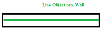
Fig(7) represent the 3d view on which we will work now. Basically i am just abandoning previously used room model and using these wall which is inside a room and consider some point as our unit origin.
Data:
Position:
Global origin co-ordinate: (0, 0, 0)-->(A)
Unit origin in global co-ordinate: (1, 1, 1)-->(B)
Panel origin in global co-ordinate: Start(1.3451, 12.1719, 0), End(11.6469, 12.1719, 0) -->(C)
1st Blockage origin in global co-ordinate: (4.8228, 12.1719, 6.5616) -->(D)
2nd Blockage origin in global co-ordinate: (10.9908, 12.2375, 6.5616) -->(E)
Window origin in global co-ordinate: (7.2506, 12, 6.7465) -->(F)
Converting to hierarchical form:
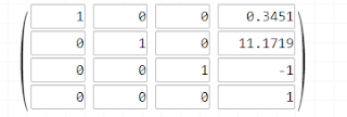
Panel w.r.t unit: ( 0.3451, 11.1719, -1) --> using (B)&(C) -->(G)
1st Blockage w.r.t to Panel: (transition from XYZ to UV)
Z component will give us the V co-ordinate. Question is which one would be our U, X or Y of XYZ ?
That can be answered if we know whether wall is parallel to X or Y.
From Start and End point of wall, we can see that wall is parallel to X axis.
Hence our blockage position will have (X, Z) == (U, V)
Figure(9) :

(D) - (C) = (4.8228, 12.1719, 6.5616) - Start(1.3451, 12.1719, 0) = (3.4777, 0, 8.8817)
1st Blockage Position = (3.4777, 6.5616)
All four corners:
leftBottom = (3.3136, 0)
leftTop = (3.3136, 13.1233)
rightBottom = (3.6417, 0)
rightTop = (3.6417, 13.1233)
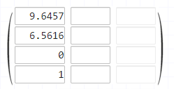
2nd Blockage w.r.t to Panel:
(E) - (C) = (10.9908, 12.2375, 6.5616) - Start(1.3451, 12.1719, 0) = (9.6457, 0.0656, 6.5616)
2nd Blockage Position = (9.6457, 6.5616)
All four corners:
leftBottom = (9.3176, 0)
leftTop = (9.3176, 13.1233)
rightBottom = (9.9738, 0)
rightTop = (9.97338, 13.1222)
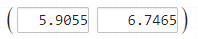
Window w.r.t to Panel:
(F) - (C) = (7.2506, 6.7465) - (1.3451, 0) = (5.9055, 6.7465)
Window Position = (5.9055, 6.7465)
All four corners:
leftBottom = (4.2651, 5.1041)
leftTop = (4.2651, 8.3849)
rightBottom = (7.5459, 5.1041)
rightTop = (7.5459, 8.3849)
Dimensions:
Panel =
[L = 10.3018, T = 0.6562, H = 13.1233]
Blockage1 =
[L = 0.3281, T = 0.6562, H = 13.1233]
Blockage2 =
[L = 0.6562, T = 0.5906, H= 13.1233]
Window =
[L = 3.2808, T = 1, H = 3.2808]
Figure(10) : Blockage co-ordinates are in UV 2d w.r.t wall

Using Matrix:
A) For unit:
It is the simplest case we dont assume rotation about x axis = 0degree.
if there is rotation in unit itself w.r.t loadcenter then we have to add that rotation about x-axis suppose.In such case matrix will include rotation component and trignometric function used can change according to that.
B) For panel:

C) For blockage1:
E) For window:
Now, how to use these matrices to reverse jump into global co-ordinates from their current coordinate system.
From particular co-ordinate system to global co-ordinate system:
For Panel->
PanelToGlobal = (A) * (B) =

For blockage1->
Blockage1ToGlobal =

For blockage2->
Blockage2ToGlobal =

For window->
WindowToGlobal =
Only converted the location point to global co-ordinate system
I guess these is enough for these post now. I want to cover, how we can draw complete shape after transforming to global co-ordinate system, because we only transformed the position. There is the thickness component haven't been considered yet.
Thanks!
posted by Pravesh Jamgade @ October 31, 2019
0 Comments
![]()


0 Comments:
Post a Comment
Subscribe to Post Comments [Atom]
<< Home